
CMU Control Joint Spacing, Locations & Details
Quick answer: For typical above-grade CMU walls built with 8-inch-high units, current CMHA empirical guidance sets both a maximum panel length-to-height ratio of 1.5:1 and a maximum control-joint spacing of 25 ft 4 in. (7.72 m). The recommendation assumes the specified minimum horizontal reinforcement. Use the smaller spacing required by the ratio or the table, then follow the project drawings and structural design. It is not a universal rule for every wall.
| Above-grade wall case | Maximum panel length-to-height ratio | Maximum joint spacing | Reinforcement condition in the guidance |
|---|---|---|---|
| CMU with 8-in. nominal unit height | 1.5:1 | 25 ft 4 in. (7.72 m) | At least 0.025 in² of horizontal reinforcement per foot of wall height |
| CMU with 4-in. nominal unit height | 1.5:1 | 20 ft (6.10 m) | At least 0.034 in² of horizontal reinforcement per foot of wall height |
| Concrete masonry veneer | 1.5:1 | 20 ft (6.10 m) | Use the reinforcement and mortar conditions specified for veneer |
These are empirical crack-control limits for the stated conditions, not structural design instructions. Wall geometry, openings, reinforcement, materials, exposure, support movement, and local experience can change the layout. Have the project designer confirm joint positions and details before construction.
How to apply the CMU spacing limit
For an 8-inch nominal-height unit, check both the panel ratio and the maximum spacing. For example, with a 12-ft-high wall, 1.5 times the height is 18 ft, which is less than 25 ft 4 in.; the ratio therefore controls the maximum panel length under the cited empirical method. With a 20-ft-high wall, the ratio gives 30 ft, so the 25-ft-4-in. maximum controls.
Measure panel height and length as defined by the project design. The maximum is not a target spacing that overrides openings, corners, wall intersections, floor or roof movement joints, or structural requirements. CMHA also says spacing may be adjusted where local experience or project conditions warrant.
What a CMU control joint does
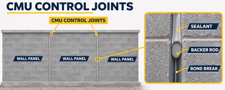
A control joint is a planned vertical plane of weakness that allows longitudinal movement and relieves stress concentrations so shrinkage-related cracking is more likely to occur at a deliberate location. A typical detail creates a bond break at the vertical joint and uses a backer rod and sealant to keep the opening weather-tight while allowing movement.
Control joints help manage shrinkage-related cracking. They do not prevent every crack and do not correct foundation settlement, excessive structural loading, poor support, or other movement outside the joint’s purpose. Read our CMU wall crack repair guide for common crack causes and next steps.
Where control joints are commonly considered
The design should consider control joints where volume changes may create stress concentrations, including:
- Changes in wall height, thickness, or stiffness
- Near one or both sides of wall openings
- Adjacent to wall corners, intersections, pilasters, recesses, or chases
- Above foundation movement joints and near movement joints in floors or roofs
Joint placement can affect the wall’s load path. A joint near an opening or lintel can change how masonry carries loads, and a control joint in a shear wall divides the wall into separate design panels. The structural designer must coordinate the location with reinforcement, lintel bearing, bond beams, and connections. See our CMU wall reinforcement guide and CMU wall height guide.
CMU control joints and reinforcement
Horizontal joint reinforcement and control joints work together in common empirical crack-control approaches. Reinforcement is generally discontinued at a standard control joint so it does not restrain the intended movement. A structural design may require a different detail or a reinforced relief joint; do not cut, continue, or terminate reinforcement based on a generic rule.
In some applications, sufficiently high horizontal reinforcement can change the crack-control approach and may make conventional control joints unnecessary. Long walls can still need reinforced relief joints, especially where the design depends on wall continuity for in-plane loads. The structural engineer must determine which approach applies. For a separate discussion of movement joints, see our CMU expansion-joint guide.
Control joints versus expansion and isolation joints
| Joint term | Typical purpose in masonry |
|---|---|
| Control joint | Divides concrete masonry into panels to accommodate shrinkage and reduce uncontrolled cracking |
| Isolation joint | Separates masonry sections to limit load transfer or accommodate differential movement |
| Expansion joint | Used primarily with clay masonry to accommodate unit expansion; typically not used in concrete masonry construction |
Project documents may use terms differently, so verify the joint’s intended function and detail. A CMU wall may need movement accommodation without the same type of expansion joint used for clay brick.
Above-grade and below-grade walls
The table at the top applies to above-grade crack-control guidance. Below-grade foundation walls traditionally do not use ordinary control joints because the joint is difficult to detail against water pressure and waterproofing requirements; temperature and moisture conditions are also more stable below grade. Follow the foundation and waterproofing design rather than transferring the above-grade spacing table to a basement wall. Our CMU wall thickness guide explains how unit width differs from finished wall depth.
Frequently asked questions
How far apart should CMU control joints be?
For typical above-grade walls using 8-inch-high units, CMHA’s empirical table gives a maximum of 25 ft 4 in. and a maximum panel length-to-height ratio of 1.5:1, with a minimum horizontal-reinforcement condition. Use the smaller applicable limit and the project design.
Does the 25-ft-4-in. limit apply to every CMU wall?
No. It is a conditional empirical recommendation for the stated unit-height and reinforcement assumptions. Four-inch-high units and concrete masonry veneer use a different listed maximum. Project conditions and engineering can require closer joints or another crack-control method.
Are control joints always required in reinforced CMU walls?
No. Reinforcement can change the crack-control approach, and sufficient horizontal reinforcement may eliminate the need for conventional control joints in some designs. Long walls may still need relief joints. The structural designer should specify the detail.
Should control joints be placed beside every door or window?
Not automatically. Openings are potential stress-concentration locations, but a joint can affect lintel bearing and wall capacity. Coordinate joint placement with the opening reinforcement, lintel, and structural design.
Are CMU control joints the same as expansion joints?
No. Control joints divide concrete masonry into panels to accommodate shrinkage; isolation joints separate sections or limit load transfer. Expansion joints are used primarily with clay masonry and are typically not used in concrete masonry construction.
Before laying out a wall
Check the wall elevations, unit height, openings, corners, support joints, horizontal reinforcement, lintels, shear-wall function, waterproofing, and specified joint sealant. Use project drawings and the structural designer’s detail for final placement. This guide explains common crack-control guidance; it does not replace engineering or code review.
Technical source note: The spacing table summarizes the CMHA 2025 Crack Control Strategies for Concrete Masonry Construction (CMU-TEC-009-25). Confirm the applicable standard edition and project requirements with the design professional.